![]()
The PID function uses system feedback to continuously control a dynamic process. The purpose of PID control is to keep a process running as close as possible to a desired Set Point.
The M90 and M91 can run 4 closed PID loops. Jazz controller loop capacity varies according to model.
A common type of control is On-Off control. Many heating systems work on this principle. The heater is off when the temperature is above the Set Point, and turns on when the temperature is below the Set Point. The lag in the system response time causes the temperature to overshoot and oscillate around the Set Point.

PID control enables you to minimize overshoot and
damp the resulting oscillations.
PID enables your controller to automatically regulate your process by:
Taking the output signal from the process, called the Process Variable (PV),
Comparing this output value with the process Set Point. The difference between the output Process Variable and the Set Point is called the Error signal.
Using the Error signal to regulate the controller output signal, called the Control Variable (CV), to keep the process running at the Set Point. Note that this output signal may be an analog or time-proportional variable value.
In the figure below, a system is regulated according to temperature.

The PID function is based on 3 actions, Proportional, Integral, and Derivative. The PID output is the combined output of all 3 actions.
All of the PID functions are activated by changes in the process Error, the difference between the Process Value and the process Set Point value (E = SP – PV).
The proportional band is a range defined around the Set Point. It is expressed as a percentage of the total Process Value (PV). When the PV is within this range, the PID function is active.
Note that the proportional band may exceed 100%. In this case, PID control is applied over the entire system range.

Proportional Action
Proportional action begins after the PV enters the proportional band; at this point, the Error is 100%. The action outputs a value that is in direct linear proportion to the size of the Error value.
A broad proportional band causes a more gradual initial response from the controller. Typically, Set Point overshoot is low; but when the system stabilizes, oscillations around the Set Point tend to be greater.
A narrow band causes a rapid response that typically overshoots the Set Point by a greater margin. However, the system does tend to stabilize closer to the set point. Note that a proportional band set at 0.0% actually forces the controller into On-Off mode.
The drawback of proportional control is that it can cause the system to stabilize below set point. This occurs because when the system is at set point, Error is zero and the control value output is therefore pegged at zero as well. The majority of systems require continuous power to run at set point. This is achieved by integrating integral and derivative control into the system.
Direct and Reverse Action
Direct action causes the output to change in the same direction as the change in Error, meaning that a positive change in Error causes a positive change in the proportional band’s output. Reverse action creates an inverse change in the output, meaning that a positive change in Error causes a negative change in output.

Integral action responds to the rate of change in the controller’s CV output relative to the change in Error. The integral time you set is the amount of time, as calculated by the controller, required to bring the process to Set Point. Note that if you set a short integral time, the function will respond very quickly and may overshoot the Set Point. Setting a larger integral time value will cause a slower response. Integral time is sometimes called Reset.
The controller’s CV output may reach and remain at 100%, a condition called saturation. This may occur, for example, if the process is unable to reach Set Point. This causes the Error signal to remain stuck in either the positive or negative range. In this situation, the integral action will grow larger and larger as the Error accumulates over time. This is called integral "wind up", which can cause the controller to overshoot the set point by a wide margin.
This situation can be prevented by setting an MB to clear the accumulated Integral error when saturation occurs.

Derivative action responds to the rate and direction of change in the Error. This means that a fast change in error causes a strong response from the controller.
The derivative action ‘anticipates’ the PV’s value in relation to the Set Point and adjusts the controller’s CV output accordingly, thus shortening the PID function’s response time.
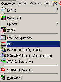
Select PID from the
Controller menu.

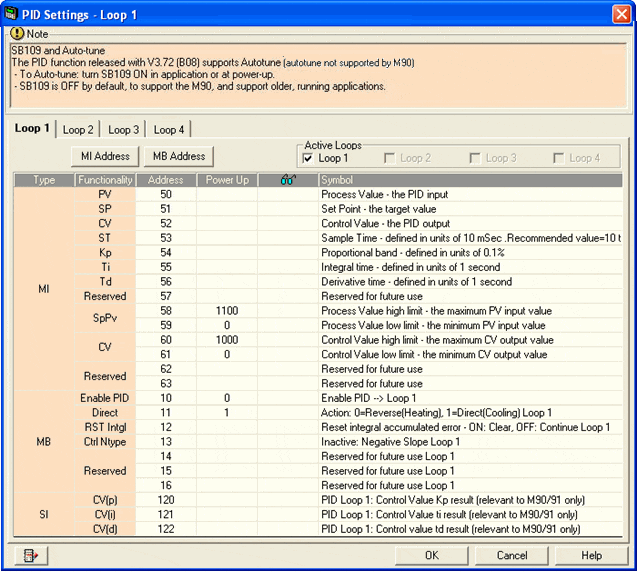
The PID parameter box opens as shown below. The parameters are
arranged in three groups. Each group is linked to a vector
of operands.
Link operands to the
PID parameters by:
-Clicking the MI Address or MB Address buttons,
OR
-Clicking a parameter;
the Select Operand & Address box opens.
Enter a vector's Start Address, then click OK; the parameters are linked to operands in that vector.
Repeat the procedure for each PID loop. Note that the number of visible loops may vary according to model.
Before you can use a PID loop, you must activate it by clicking the appropriate check box under Active Loops.

Operand |
Parameters |
Function |
MI |
PV: |
PV is the feedback from the process. PV is output from the process and input to the PID function. In a heating system, the temperature measured by a temperature sensor provides the PV. |
SP: |
SP is the target value for the process. In a heating system, this is the temperature value set for the system. Note that the Set Point and Process value must be given in the same type of units (degrees Celsius, bars, meters per second, etc.) |
|
CV: |
CV is the output from the PID function. CV is output from the PID function and input to the process. Note that this output signal may be an analog or time-proportional variable value. |
|
ST: |
Use this parameter to define the intervals between PID function updates, in units of 10mSecs. |
|
Kp: |
Use this parameter to define the proportional band, in units of 0.1%. The proportional band is a percentage of the total Process Value (PV). It is a range defined around the Set Point. When the PV is within this range, the PID function is active. |
|
Ti: |
Use this parameter to define the integral time, in units of 1 second. Integral action responds to the rate of change in the controller’s CV output relative to the change in Error. The integral time you set is the amount of time, as calculated by the controller, required to bring the process to Set Point. |
|
Td: |
Use this parameter to define the derivative time, in units of 1 second. Derivative action responds to the rate and direction of change in the Error. This means that a fast change in error causes a strong response from the controller. The derivative action 'anticipates’ the PV’s value in relation to the Set Point and adjusts the CV accordingly, thus shortening the PID function’s response time. |
|
Reserved |
Reserved for future use. |
|
SPPV: |
High: Use this parameter to define the upper limit for the Process Value. |
|
Low: Use this parameter to define the lower limit for the Process Value. |
||
CV: |
High: Use this parameter to define the upper limit for the Control Value. |
|
Low: Use this parameter to define the lower limit for the Control Value. |
||
Reserved |
Reserved for future use. |
|
MB |
Enable PID |
Use this parameter in your program to turn the PID loop on and off. ON activates PID action: OFF deactivates PID action. |
Reverse |
Use this parameter in your program to control PID output direction. Off activates Reverse Action, ON activates Direct Action. Direct action causes the output value to change
in the same direction as the change in PV.
Note ♦ In the case of a temperature control application, Reverse Action is heating, Direct Action is cooling. |
|
RST INTGL: |
Use this parameter to clear integral error. If the system does not reach setpoint within the time defined in the parameter Intgl. Time, Integral error occurs and may increase. Use this parameter to prevent the error from growing large enough to interfere with the Integral operation. |
|
Ctrl Ntype: |
Negative slope control. When the system is 'cooling' down, this helps to control undershoot and stabilize oscillations around the setpoint. When the MB is OFF, Negative Slope Control
is ON; when the MB is ON, Negative Slope Control is
suspended. |
|
Reserved |
Reserved for future use. |
|
Reserved |
Reserved for future use. |
|
SI |
CV(P): |
This is the Proportional component of the PID function, calculated by the controller. |
CV(I): |
This is the Integral component of the PID function, calculated by the controller. |
|
CV(P): |
This is the Derivative component of the PID function, calculated by the controller. |
You can auto-tune M90 PID loops by using Unitronics PID Server. This utility is located under the Tools menu.
As of V3.72 (B08), M91 controllers may be tuned via SBs.
Here is a common method that may be used to manually tune PID loops.
Kp
|
|
Ti |
Once the Kp value has been optimized, adjust the Ti value. In most applications, once the Kp has been optimized, the system can reach setpoint via adjusting the Ti parameter. The goal is to use this parameter to reach the setpoint as quickly as possible without overshoot. In many applications,
a starting value of 300 (Sec) is appropriate. If the time
interval before the system reaches reach setpoint is too long,
decrease the Ti. If the time interval is too short, overshoot
will occur. In this event, increase the Ki value. |
Td |
If your system requires a rapid PID response, such as to sharp changes in temperature, use the Td parameter. The higher the value, the more quickly the system will react. A high value may cause overshoot. In most applications, a Td value of 0-30 (sec) is appropriate. In most cases, the Td value will be between 0-20. |
Note ♦ |
The recommended value for the ST (Sample Time) parameter is 100 ( ST=100). |
Related Topics