You can implement motor control by controlling the high-speed outputs of certain Vision controllers, and the EXF-RC15 Remote I/O, using PTO functions, controlling up to three independent axes.
In this way you can, for example, build speed profiles that are appropriate for stepper motors. Note that the PTO control functions are open-loop, and do not rely on positional feedback.
Pulse
Uses a single high-speed output
Pulse + Direction
Uses 2 high-speed outputs, one for the pulse, and the second to control direction
Clockwise/Counter Clockwise
Uses 2 high-speed outputs, one for clockwise, the other for counter-clockwise
A Channel comprises the outputs that are required to implement a Mode.
The number of channels, the possible modes, and the outputs used to implement them vary from model to model. The following tables show the possible combinations, according to Vision model.
|
Notes ♦ |
When an Output is not being used in a channel, it may be used as a general-purpose output (not high-speed) |
|
Caution |
These functions are based on programming logic, and therefore do not have the safeguards generally provided by electro-mechanical controls. It is the user's responsibility to implement those safeguards required by his system, such as override and/or emergency stop mechanism. |
V130/V350-TR34/EXF-RC15
|
Channel |
Possible Mode Combinations |
||||
|
Channel 0 |
Pulse |
Pulse + Direction |
Pulse + Direction |
Pulse |
Clockwise/Counter Clockwise |
|
Channel 1 |
Pulse |
Pulse + Direction |
Pulse |
Pulse + Direction |
Disabled |
|
Channel 2 |
Pulse |
Disabled |
Disabled |
Pulse |
Pulse |
|
Channel |
Outputs used per Channel |
||||
|
Channel 0 |
Pulse (O0) |
Pulse (O0) + Direction (O2) |
Pulse (O0) + Direction (O2) |
Pulse (O0) |
Clockwise (O0) / Counter Clockwise (O1) |
|
Channel 1 |
Pulse (O1) |
Pulse (O1) + Direction (O3) |
Pulse (O1) |
Pulse (O1) + Direction (O3) |
Disabled |
|
Channel 2 |
Pulse (O2) |
Disabled |
Disabled |
Pulse (O2) |
Pulse (O2) |
V130/V350-TRA22
The following table shows all of the possible PTO mode combinations for this model.
|
Channel |
Possible Mode Combinations |
||||
|
Channel 0 |
Pulse |
Pulse + Direction |
Pulse + Direction |
Pulse |
Clockwise/Counter Clockwise |
|
Channel 1 |
Pulse |
Pulse + Direction |
Pulse |
Pulse + Direction |
Disabled |
|
Channel |
Output used per Channel |
||||
|
Channel 0 |
Pulse (O0) |
Pulse (O0) + Direction (O2) |
Pulse (O0) + Direction (O2) |
Pulse (O0) |
Clockwise (O0) / Counter Clockwise (O1) |
|
Channel 1 |
Pulse (O1) |
Pulse (O1) + Direction (O3) |
Pulse (O1) |
Pulse (O1) + Direction (O3) |
Disabled |
V130/V350-TR20, TR6
|
Channel |
Possible Mode Combinations |
||
|
Channel 0 |
Pulse |
Pulse + Direction |
Clockwise/Counter Clockwise |
|
Channel 1 |
Pulse |
Disabled |
Disabled |
|
Channel |
Output used per Channel |
||
|
Channel 0 |
Pulse (O6) |
Pulse (O6) + Direction (O7) |
Clockwise (O6) / Counter Clockwise (O7) |
|
Channel 1 |
Pulse (O7) |
Disabled |
Disabled |
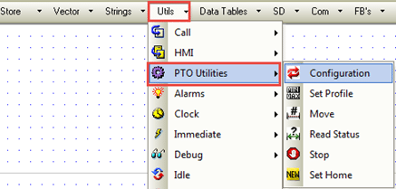
These are located on the Ladder toolbar, under the Utils menu.
In this function you select a Vision model, which determines the available Channels and Modes. Those not available are disabled.

|
Parameter Name |
Purpose |
|
Vision Model |
Select the appropriate model |
|
Channel |
A Channel comprises the inputs used to carry out the PTO function, and determines their function |
|
Mode |
The possible modes are:
The tables in the previous section give all possible combinations and output assignments, based on model. |
|
Switch |
Switch reverses the tasks of the PTO outputs that are assigned to the channel in modes Pulse + Direction or CW/CCW. This can be helpful to fix cases where the output wiring is reversed. |
|
Unit |
PTO functions rely on Units. This is where you determine the number of pulses per Unit. Note that neither values for Unit nor Pulses per Unit may exceed 1000 Note - To control your output using straight frequency, set 1 pulse = 1 unit. Calculate Frequency to Units according to the following
|
|
Status Messages |
0 - No error 1 - Invalid configuration data 2 - VisiLogic/OS mismatch; this OS version 3 - Vision outputs do not support function 4 - Invalid structure 5 - Invalid configuration channel 6 - Unit or Pulse per Unit exceed limits (1-1000) 7 - Channel already initialized 8 - Currently in motion ( function cannot be performed during acceleration or deceleration) |
|
Success Bit |
Turns ON when the Status MI =0 |
Use Set Profile to define the motion profile for a particular Channel in the configuration.

Note the minimum and maximum ranges for your motion profile.
|
Range |
Minimum |
Maximum |
|
1 |
5 Hz |
15 kHz |
|
2 |
10 Hz |
20 kHz |
|
3 |
305 Hz |
133 kHz |
|
4 |
610 Hz |
200 kHz |
|
Parameter Name |
Purpose |
|
Channel |
Select the relevant channel |
|
Start/ Stop Velocity |
These parameters determine the limits of the motion profile for the channel. Note that the resolution of velocity is according to the units set in the PTO Configuration.
|
|
Maximum Velocity |
|
|
Acceleration Time (mS) |
|
|
Deceleration Time (mS) |
|
|
Jerk Factor |
Controlling for jerk influences the shape of your motion curve. Legal values are from 1 to 16, where 1=trapezoidal curve and 16 =perfect S. |
|
Status Messages |
0 - OK 1 - Invalid configuration data 2 - Currently in motion ( function cannot be performed during acceleration or deceleration) 3 - Invalid channel 4 - PTO Configuration block does not exist 5 - Out of range 6 - Maximum value is out of range |
|
Success Bit |
Turns ON when the Status MI =0 |
In this function you determine the parameters of movement.

|
Parameter Name |
Purpose |
|
Channel |
Select the relevant channel |
|
Movement Type |
This sets the type of movement:
|
|
Velocity |
Note that the resolution of velocity is according to the units set in the PTO Configuration. The Move velocity must be greater than the Start/Stop velocity |
|
Target Position |
Sets the desired goal |
|
Status Messages |
0 - Idle / OK 1 - Configuration data is invalid 2 - Invalid channel 3 - Channel not initialized, or Vision outputs do not support function 4 - Absolute Movement cannot be performed 5 - Currently in motion ( function cannot be performed during acceleration or deceleration) |
|
Success Bit |
Turns ON when the Status MI =0 |
Use this to stop movement

|
Parameter Name |
Purpose |
|
Channel |
Select the relevant channel |
|
PTO Stop |
|
|
Status Messages |
0 - Idle / OK 1 - Already stopped 2 - Invalid channel 3 - Channel isn’t initialized 4 - unknown command |
|
Success Bit |
Turns ON when the Status MI =0 |
Use this to ascertain the current position.

|
Parameter Name |
Purpose |
|
Channel |
Select the relevant channel |
|
Current Position |
Use these as a reference for Move functions Note that the resolution of velocity is according to the units set in the PTO Configuration |
|
Velocity |
|
|
In Progress |
This turns Off after the values have been read. |
|
Status Messages |
0 - Idle / OK 1 - Currently in motion ( function cannot be performed during acceleration or deceleration) 2 - Channel is not configured 3 - Invalid channel 4 - Read Timeout |
|
Success Bit |
Turns ON when the Status MI =0 |
Use this to set a Home position for Move operations set to Absolute Position

|
Parameter Name |
Purpose |
|
Channel |
Select the relevant channel |
|
Offset: PTO Set Home |
The channel uses this value to set the reference point for the next move operation. If, for example, the Absolute target is set to 600, and the Offset to 200, the channel will move to 400. |
|
Status Messages |
0 - OK 1 - invalid channel 2 - precondition error 3 - Channel is currently accelerating or decelerating ( Movement can only be performed when system is Idle of in steady state) |
|
Success Bit |
Turns ON when the Status MI =0 |
