


Multi-function Programmable Logic Controller + HMI Overview
- Auto-tune PID, up to 24 independent loops
- Recipe programs and data logging via data tables
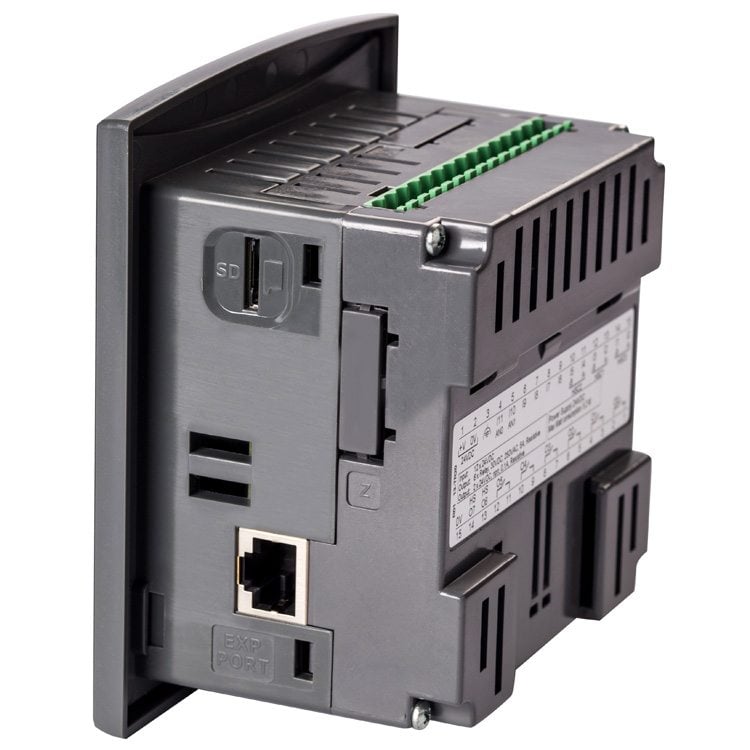
- Micro SD card – log, backup, clone & more
- Function Blocks
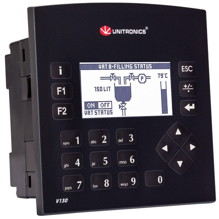
- Monochrome
- Multi-language display
- Built-in Alarm Screens
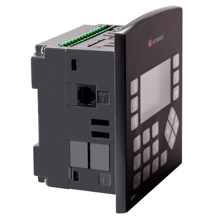
- RS485/ RS232
- 2 ports may be added: 1 Serial/Ethernet/Profibus and 1 CANbus
Protocols:
- MODBUS TCP
- SNMP*
- CANopen, CANlayer2, UniCAN
- BACnet, KNX and M-Bus via gateway
- FB Protocol: for any 3rd party protocol
General Features: Web server, E-mail & SMS, 3G Modem support, Remote access utilities
* SNMP V1 Trap, SNMP community Name
- Expand up to 256 I/Os
- I/O options include digital, analog, high-speed, temperature & weight measurement. See tables below:
Visilogic™ Software for Vision130™
All-in-One programming environment. Simple, fast development for both Ladder and HMI applications.
- Develop your programmable logic controller (PLC ) and HMI applications in one environment
- Configure hardware & communications
- Establish modem and data communications
- Test and debug your programs
- Software Utilities Suite: remote access and data management tools
Document Downloads
Installation Guide
File NameDownload File
V130-33-B1/ V130-J-B1Download
V130-33-TR20/ V130-J-TR20Download
V130-33-R34/ V130-J-R34Download
V130-33-TR6/ V130-J-TR6Download
V130-33-RA22/ V130-J-RA22Download
V130-33-TRA22/ V130-J-TRA22Download
V130-33-T2/ V130-J-T2Download
V130-33-T38/ V130-J-T38Download
V130-33-TA24/ V130-J-TA24Download
V130-33-TR34/ V130-J-TR34Download
Technical Specifications
File NameDownload File
V130-33-B1/ V130-J-B1Download
V130-33-TR20/ V130-J-TR20Download
V130-33-R34/ V130-J-R34Download
V130-33-TR6/ V130-J-TR6Download
V130-33-RA22/ V130-J-RA22Download
V130-33-TRA22/ V130-J-TRA22Download
V130-33-T2/ V130-J-T2Download
V130-33-T38/ V130-J-T38Download
V130-33-TA24/ V130-J-TA24Download
V130-33-TR34/ V130-J-TR34Download
3D Drawings
Success stories


What does Vision130™ look like?
Watch the Vision130™ unpacking video.